Before I started this repair, the combination gauge with the compass and acceleration readout didn’t do anything — the arrows and backlight didn’t even light up. Here’s an overview of what I did to get them working.
Backlights
The backlights were a pretty easy fix. One or two bulbs were dead while the others just had corrosion on the contacts. I removed all of the bulbs and swapped them for LEDs (4× 74-GHP3: Green from Super Bright LEDs). I also took high-grit sandpaper (~600) and cleaned the contacts until they had a slight shine. After that, all good.
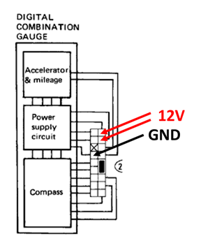
You can power up the unit by applying 12V to the correct leads. The LED lighting is less evenly distributed than incandescent, but it runs much cooler and draws very little current. There were actually melt/burn marks on some of the plastic from the original incandescents.
Firing Up the VFDs
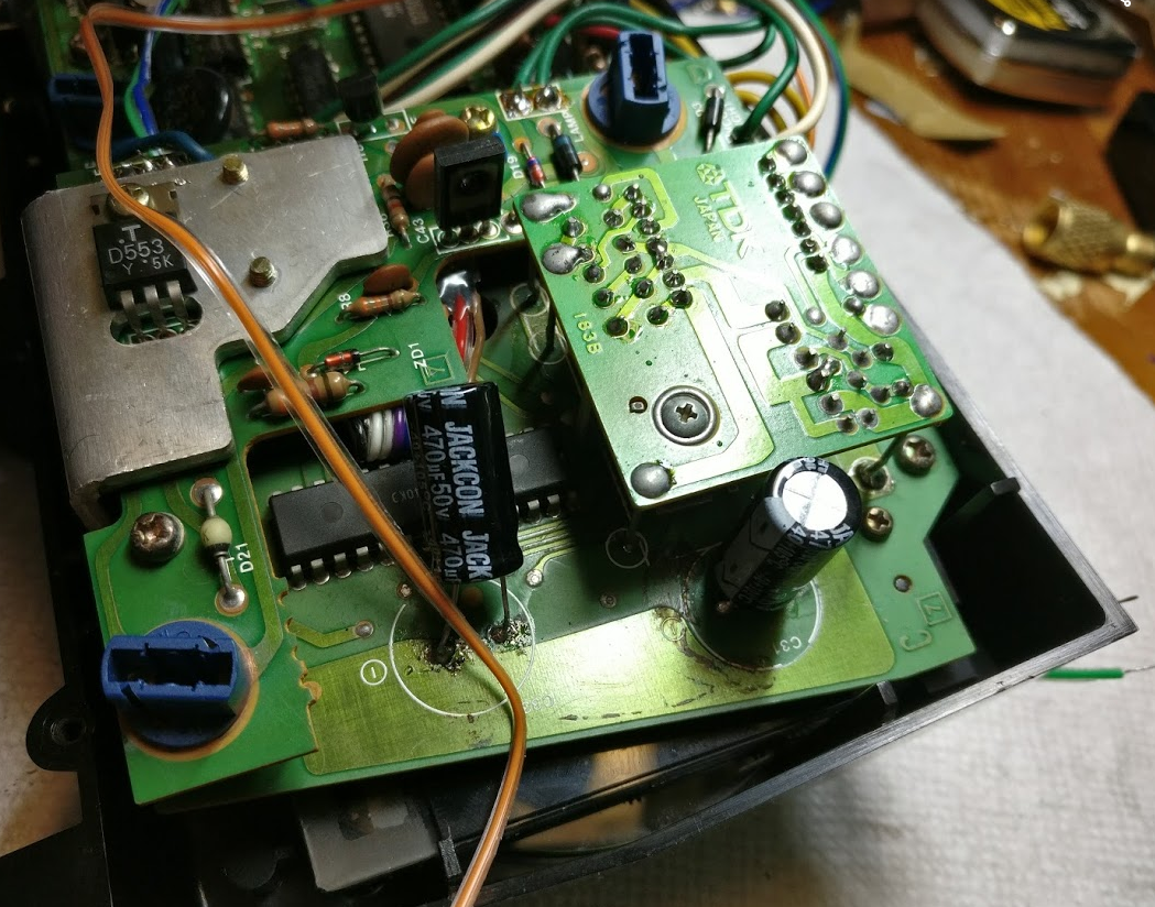
At this point the VFDs (vacuum fluorescent displays) didn’t turn on at all, so I opened up the case and started poking around on the PCBs. I quickly found that the two large capacitors had leaked and were long dead. After scraping off the residue and cleaning with IPA, I replaced them.
Tip on desoldering: Grab the old caps with pliers and rotate one way then the other to rip them off the leads. Then use a soldering iron to clean up the leads. The alternative is desoldering from the bottom but that requires separating the two boards enough to access the underside of the top board — much harder.
You can solder in new caps from the top — just apply heat long enough that solder flows down through the hole. Any electrolytic capacitor rated 470 µF and 35V+ will work. I got these at Microcenter for about $4 total.
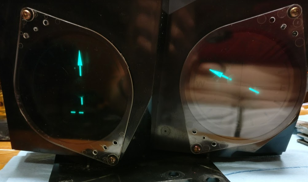
After replacing the caps the VFDs lit up. The compass worked! However, the acceleration and mpg gauges did not.
Diagnosing the Acceleration Gauge
The FSM describes how to check the input signals to the gauge. I went through those checks — all signals looked good. The gauges were receiving correct data but not responding to it. Back to the PCBs.
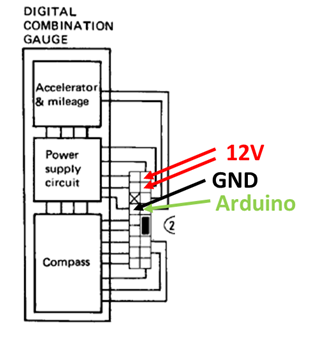
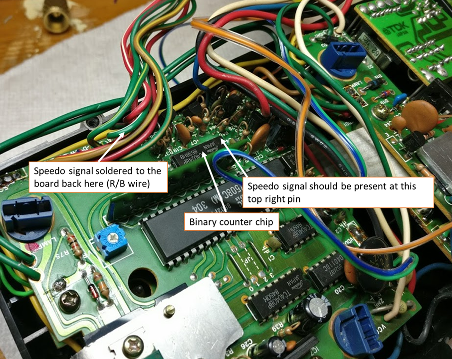
To diagnose further I needed to simulate the car’s speed sensor so I could work on the gauge on my bench. The speed sensor is essentially an LED + optical encoder. You supply 5V for the LED and the output is a digital square wave — frequency is directly proportional to vehicle speed.
I wired up an Arduino to output a 5V digital signal that simulates acceleration and deceleration from −0.5 to +0.5 g. The FSM notes the encoder is divided by 24, so each wheel revolution produces 24 pulses.
| Time (s) | Accel (g) | Speed (mph) | Freq (Hz) | Period (ms) |
|---|---|---|---|---|
| 0.1 | 0.01 | 0.0 | 0.1 | 7046 |
| 1.0 | 0.10 | 1.2 | 7.8 | 128 |
| 2.0 | 0.20 | 4.6 | 29.8 | 34 |
| 3.0 | 0.30 | 10.2 | 66.0 | 15 |
| 4.0 | 0.40 | 18.0 | 116.4 | 9 |
| 5.0 | 0.50 | 28.0 | 180.9 | 6 |
The Arduino starts sending very slow pulses and speeds them up over 5 seconds to simulate acceleration.
// Simulate 300ZX speed sensor signal to test compass/accel gauge
// Digital pin 13 outputs the signal
// Ramps from ~0 mph to ~28 mph over 5 seconds, then back down

const int signalPin = 13;

// Period values (ms) corresponding to speeds in the table
int periods[] = {7046, 128, 34, 15, 9, 6};
int numSteps = 6;

void setup() {
  pinMode(signalPin, OUTPUT);
}

void loop() {
  // Accelerate
  for (int i = 0; i < numSteps; i++) {
    unsigned long stepEnd = millis() + 1000; // hold each step for ~1s
    while (millis() < stepEnd) {
      digitalWrite(signalPin, HIGH);
      delay(periods[i] / 2);
      digitalWrite(signalPin, LOW);
      delay(periods[i] / 2);
    }
  }
  // Decelerate
  for (int i = numSteps - 1; i >= 0; i--) {
    unsigned long stepEnd = millis() + 1000;
    while (millis() < stepEnd) {
      digitalWrite(signalPin, HIGH);
      delay(periods[i] / 2);
      digitalWrite(signalPin, LOW);
      delay(periods[i] / 2);
    }
  }
}
With this test rig I was able to confirm the gauge was responding correctly to the speed signal and track down the remaining issue on the PCB.
Result
The compass and gauge are now fully functional and reinstalled in the car.