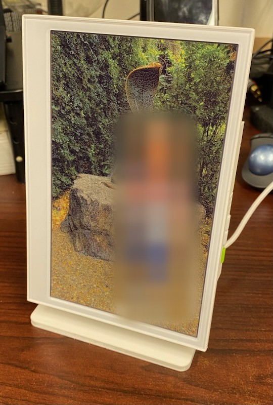
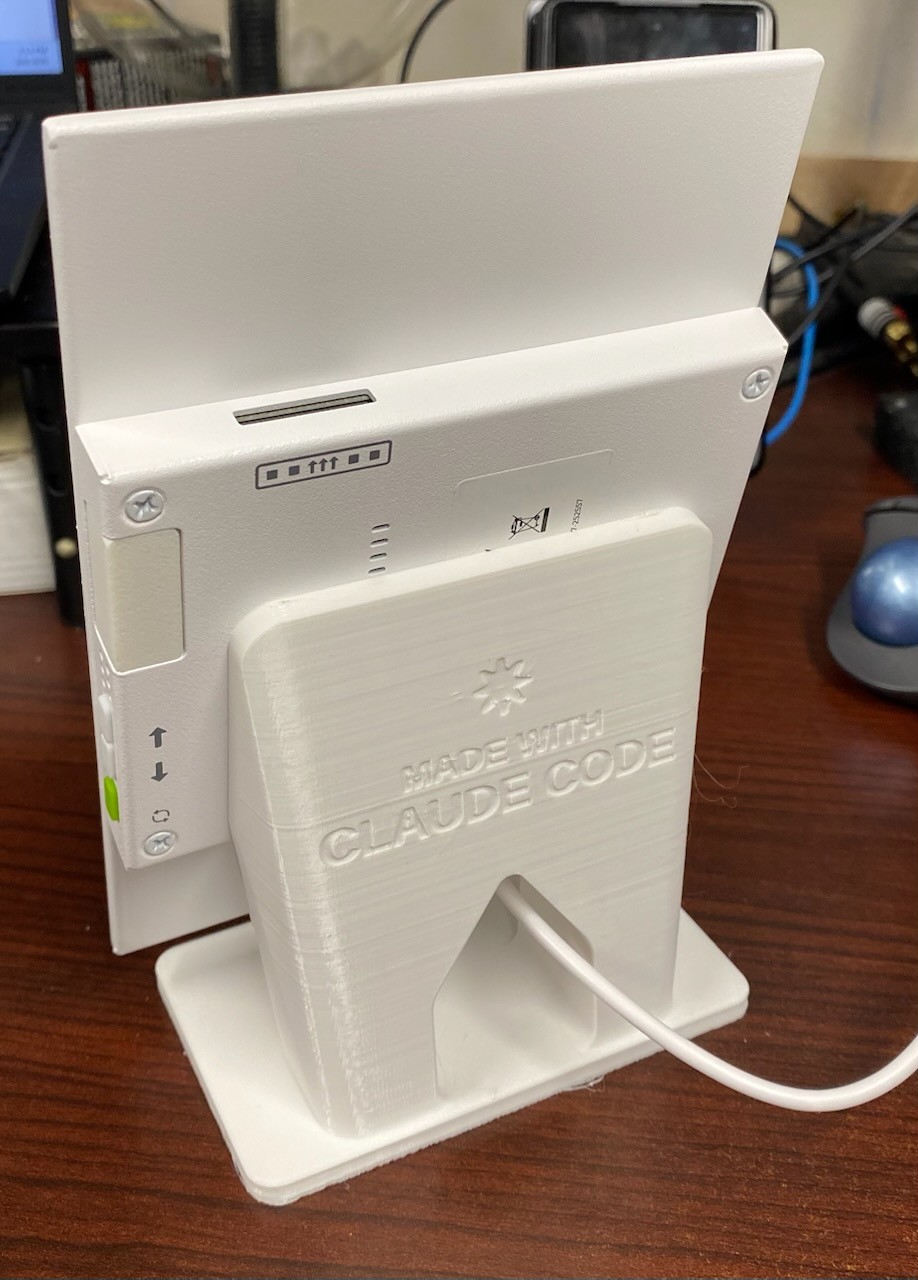
A desk stand that holds a Seeed reTerminal E1002 e-paper frame in portrait as a digital picture frame. It was designed in OpenSCAD with Claude Code and printed in PETG on an Ender-3, all on 6 September 2026.
The brief
The initial prompt:
lets model a digital picture frame stand to hold seeed studio E1002 in portrait orientation. they provide a model here https://files.seeedstudio.com/wiki/reterminal_e10xx/res/reTerminal_E1001_E1002_3D.stp which may be helpful
And two minutes later:
and a goal will be to keep the center of mass of the E1002 centered over the portrait stand’s footprint
Iterations
The renders come from each committed version of e1002_portrait_stand.scad, shown with the device model in place. Each card has a strip of alternate views: click one to swap it into the large render.
First pass
The first session produced a first-pass cradle but modelled the E1002 wrongly. That geometry was never committed, so it can’t be rendered. The geometry was then corrected:
it’s basically two rectangular prisms unioned. one for the display (fairly thin) and one for the electronics (fairly thick)
The vendor STEP file was saved as a reference, and the cradle design carried into Rev 1.
1
Angled cradle
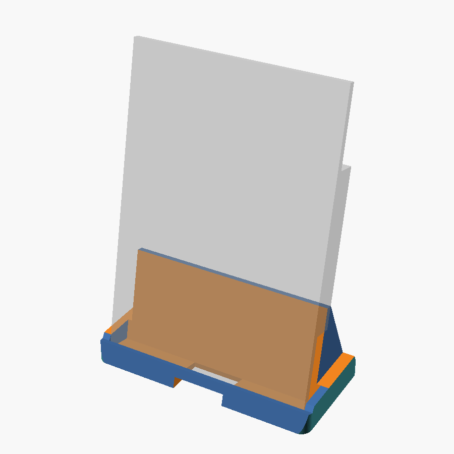
- The device model is now correct: a 175 × 120 × 4 mm display slab plus a 119.2 × 87.4 × 13 mm electronics block, measured off the vendor STEP.
- The back-panel wall-hang keyhole was located.
- The stand is still the first-pass cradle. The device drops into an angled channel, and a tail behind the backrest puts the centre of mass over the footprint’s centroid.
2
Floating frame on a keyhole peg
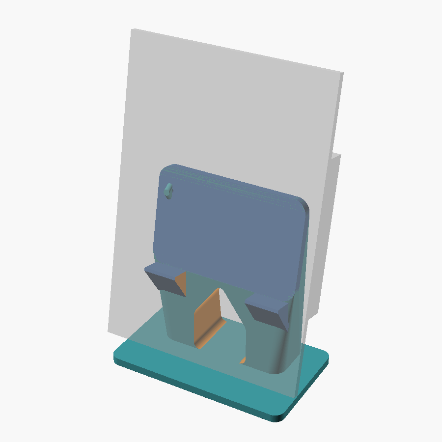
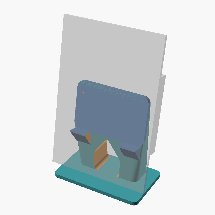
lets rework the photo frame stand… i want the stand to support the frame mostly at the electronics enclosure… the frame itself should almost be ‘floating’… and then we’d use the keyhole to help key the stand to teh frame
- The cradle was replaced by a column. A ledge under the block takes the weight, a pad behind it takes the lean, and the display touches nothing.
- A peg on the pad engages the device’s keyhole. Sliding the device 8 mm sideways brings it to a hard stop, which is the centred position.
- The arched window is gabled so it never overhangs past 45°. The engraved “Made with Claude Code” mark sits in the band above it.
A later commit, b871e6c (19:30), changed only a comment in the file.
3
Peg split off as a glued-in part
the keyhole knob - can we print it separately and i’ll glue it on after? ideally when you split the 2 parts you should leave an indentation on the main body that makes the keyhole knob index into position naturally
- The peg is its own part now. It glues into a round socket with a flat across the top, so it only goes in one way. The flat also lets the socket’s ceiling bridge 4.5 mm.
- The peg printed first and fit the real keyhole on the first try. A later commit, 32585da (22:51), recorded the fit test with no change to the geometry.
- The stand body was re-sliced and sent to the printer at 23:57.
Timeline
| When | What happened |
|---|---|
| The frame: firmware and photo app | |
| 08-27 | The original brainstorm: a frame for work that refreshes every ~2 hours, with photos served from a Pixel 6 via Tasker. |
| 08-31 | The device arrived and was powered on. |
| 09-01 – 09-06 | Tasker sync, ROI cropping, refresh trigger and flashing. |
| The stand | |
| 09-06 15:18 | Initial prompt, the centre-of-mass goal and a first pass. |
| 09-06 15:48 | Device model fixed to two prisms and keyhole found. Rev 1. |
| 09-06 16:00 | Stand reworked around the electronics block and keyhole, then the maker's mark and arch added. Rev 2. |
| 09-06 19:57 | Print time estimated at three layer heights. That led to a spool-tracking tool for the printer. |
| 09-06 21:19 | Filament on the spool checked, then the peg split off. Rev 3. |
| 09-06 22:10 | Both parts checked for printability and orientation. The peg print started. |
| 09-06 22:49 | The peg fit the real keyhole, and the fit was recorded. |
| 09-06 23:57 | Stand body re-sliced and printed. |